
- Sunrise Electric Motor Company
Quality Guarantee
 Home > News
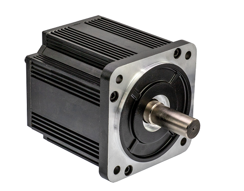
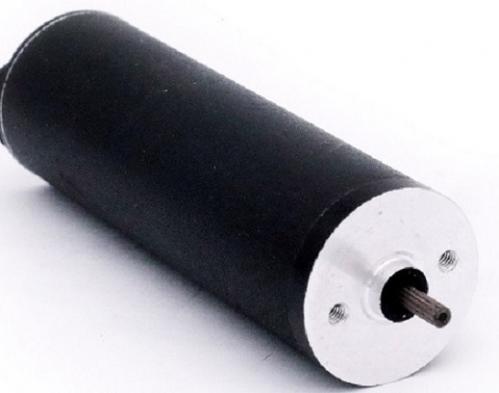
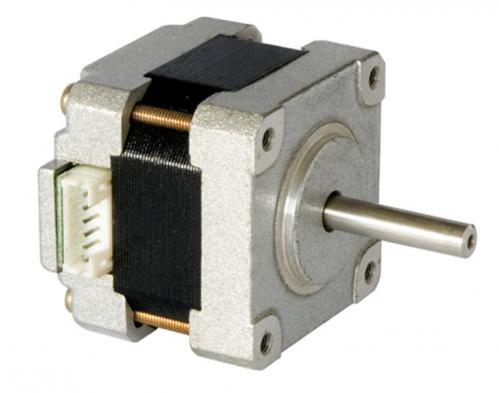
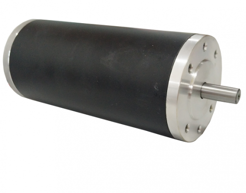
Servomotor controllers have become more than just amplifiers for a servomotor. Today servomotor controllers must be able to make a number of decisions and provide a means to receive signals from external sensors and controls in the system, and send signals to host controllers and PLCs that may interface with the servo system. Figure 11-87 shows a picture of several servomotors and their amplifiers. The components in this picture look similar to a variety of other types of motors and controllers.
Figure 11-88 shows a diagram of the servomotor controller so that you can see some of the differences from other types of motor controllers. The controller in this diagram is for a DC servomotor. The controller has three ports that bring signals in or send signals out of the controller. The power supply, servomotor, and tachometer are connected to port P3 at the bottom of the controller. You can see that the supply voltage is 115-volt AC single phase. A main disconnect is connected in series with the LI wire. The LI and N lines supply power to an isolation step-down transformer. The secondary voltage of the trans-former can be any voltage between 20 and 85 volts. The controller is grounded at terminal 8. You should remember that the ground at this point is only used to provide protection against short circuits for all metal parts in the system.
The servomotor is connected to the controller at terminals 4 and 5. Terminal 5 is + and terminal 4 is —. Terminal 3 provides a ground for the shield of the wires that connect the motor and the controller. The tachometer is connected to terminals 1 and 2. Terminal 2 is + and terminal 1 is —. The shield for this cable is grounded to the motor case. The wires connected to this port will be larger than wires connected to the other ports, since they must be capable of carrying the larger motor current. If the motor uses an external cooling fan, it will be connected through this port. In most cases the cooling fan will be powered by single-phase or three-phase AC voltage that remains at a constant level, such as 110 volts AC or 240 volts AC.
The command signal is sent to the controller through port PI. The terminals for the command signal are 1 and 2. Terminal 1 is + and terminal 2 is —. This signal is a type signal, which means that it is not grounded or does not share a ground potential with any other part of the circuit. Several additional auxiliary signals are also connected through port 1. These signals include inhibit (INH), which is used to disable the drive from an ex-ternal controller, and forward and reverse commands (FAC and RAC), which tell the con-troller to send the voltage to the motor so that it will rotate in the forward or reverse direc-tion. In some applications, the forward maximum travel limit switch and reverse maximum travel limit switch are connected so that if the machine travel moves to the extreme posi-tion so that it touches the overtravel limit switch, it will automatically energize the drive to begin travel in the opposite direction.
Port PI also provides several digital output signals that can be used to send fault signals or other information such as "drive running" back to a host controller or PLC. Port PI basically is the interface for all digital (on-off) signals.
Port P2 is the interface for analog (0-max) signals. Typical signals on this bus include motor current and motor velocity signals that are sent from the servo controller back to the host or PLC where they can be used in verification logic to ensure the con-troller is sending the correct information to the motor. Input signals from the host or PLC can also be sent to the controller to set maximum current and velocity for the drive. In newer digital drives, these values are controlled by drive parameters that are programmed into the drive.


 0086-519-88298833


View More(Total0)Comment Lists